How to Avoid Low Voltage Lighting Failures: The Editorial Guide
The engineering of low-voltage exterior lighting represents a paradox of modern landscaping: it is ostensibly the safest and most accessible form of illumination to install, yet it is simultaneously the most prone to systemic degradation. In a 12V or 24V environment, the margin for error in electrical continuity is significantly narrower than in standard 120V line-voltage systems. Where a slight increase in resistance might be negligible in a house circuit, it can cause a low-voltage fixture to flicker, dim, or vanish entirely. How to Avoid Low Voltage Lighting Failures. This fragility is often masked by the “plug-and-play” marketing of consumer-grade kits, which ignore the relentless physics of the outdoor environment.
To approach the longevity of these systems, one must recognize that a landscape is not a static gallery but a slow-motion hydraulic and chemical engine. Soil shifts, roots expand, and moisture permeates every microscopic fissure in a wire’s jacket. Consequently, the failure of a lighting array is rarely a singular event of a bulb “burning out.” It is almost always a cumulative breakdown of the transmission network—the invisible infrastructure of transformers, hubs, and splices that must maintain a precise voltage window over hundreds of feet of varying terrain.
Achieving topical mastery in the prevention of these outages requires a shift from cosmetic design to “infrastructure-first” planning. It is an exercise in managing resistance, heat, and oxidation. When we discuss professional-grade resilience, we are looking at the delta between a system that lasts three seasons and one that survives for three decades. This editorial inquiry deconstructs the mechanics of electrical decay and the specific, rigorous protocols required to ensure an outdoor lighting asset remains a permanent fixture of the property’s architectural value.
How to avoid low voltage lighting failures
To master how to avoid low voltage lighting failures, one must first dismantle the prevailing myth that low voltage is “low maintenance.” In reality, the lower the voltage, the higher the sensitivity to physical variables. A multi-perspective view reveals that “failure” is often a gradual drift rather than a sudden darkness. For instance, “Voltage Drop” is the primary antagonist; as electricity travels down a copper wire, it loses energy to resistance. If a 12V transformer is pushing power to a light 100 feet away, and that light only receives 10.5V, the LED driver may overheat as it tries to compensate, or a halogen bulb will shift toward a sickly yellow spectrum, eventually failing prematurely.
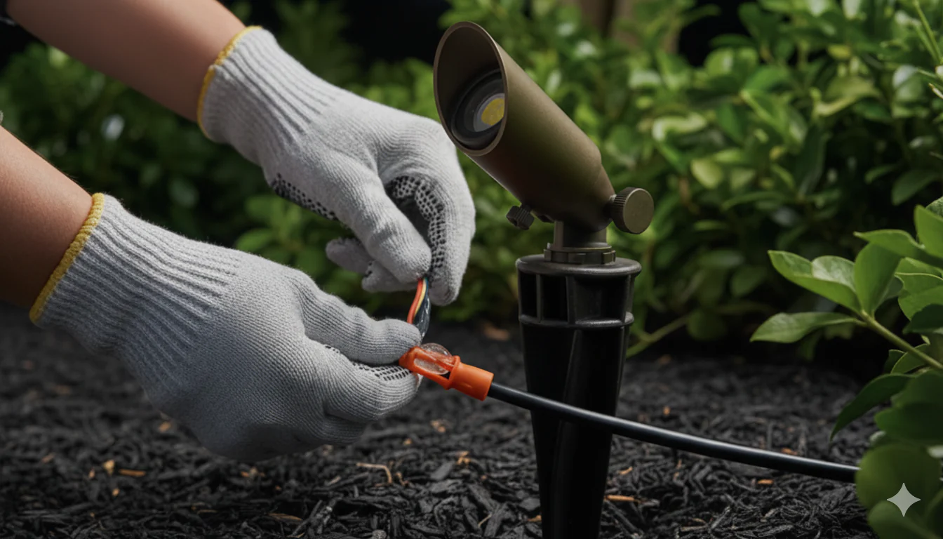
A primary misunderstanding in the field is the reliance on “pierce-point” connectors—those plastic clips that bite into the wire. Oversimplification leads many to believe these are permanent solutions. In truth, every puncture in a wire’s insulation is an invitation for “green rot” (copper oxidation). As moisture wicks into the puncture, the copper turns into a non-conductive powder. Knowing how to avoid low voltage lighting failures involves a commitment to hermetic seals: using tinned-copper wire and “direct-burial” grease-filled lugs that treat every connection as a potential site for a chemical short-circuit.
The risk of an uncoordinated system is “thermal stress.” Modern LED chips are exceptionally efficient but are highly sensitive to the quality of the incoming current. If a transformer is “over-tapped”—sending 15V to compensate for a long run—the fixtures closest to the power source will receive an over-voltage that degrades the delicate semi-conductors. True prevention lies in “Zone Balancing,” a strategy where the property is divided into independent runs, each calculated to deliver exactly 11.5V to 12V to every single node, regardless of its distance from the hub.
The Socio-Technical Context: The Evolution of 12V Systems
The history of low-voltage lighting is a chronicle of safety winning over sheer power. In the mid-20th century, outdoor lighting was primarily line-voltage (120V), which required deep trenching, rigid conduit, and expensive union labor. It was inherently dangerous; a stray shovel hit could be fatal. The introduction of the 12V transformer in the 1960s democratized the landscape, allowing for “direct burial” cables that could be tucked under mulch. However, these early systems were limited by the massive “voltage drop” of incandescent bulbs, which drew significant amperage.
The “LED Revolution” of the 2010s fundamentally changed the physics of the industry. Because LEDs draw approximately 80% less current than halogens, they theoretically allowed for much longer wire runs and smaller transformers. Yet, this efficiency introduced a new failure mode: “Electronic Noise.” Modern LED drivers are essentially small computers; they can be “confused” by electromagnetic interference or “dirty” power coming from a cheap magnetic transformer.
Today, we are in the era of “Smart Transformers” and tinned-wire infrastructure. The evolution has moved from “Can we get light out there?” to “How do we ensure the digital driver inside this light survives a decade of humidity and voltage fluctuations?” The focus has shifted from the bulb to the “Loop Architecture”—the way we move electrons through a hostile, wet environment.
Conceptual Frameworks: Mental Models for Electrical Resilience
Professionals utilize specific frameworks to visualize the invisible forces that degrade a system.
1. The “Water Pipe” Analogy (Ohm’s Law)
Think of Voltage ($V$) as water pressure and Amperage ($I$) as the flow rate.
-
The Failure: If the pipe (wire) is too thin (high gauge), the pressure (voltage) drops by the time it reaches the end.
-
The Defense: Using 10-gauge or 12-gauge “fat” wires for the main “home runs” to maintain pressure.
-
Limit: Over-sizing wire adds significant material cost and can be difficult to terminate in small fixtures.
2. The “Point-of-Entry” Hermeticism Model
This framework posits that the system is only as strong as its weakest splice.
-
The Failure: Moisture wicking.
-
The Defense: Treating the wire jacket as a sacred barrier. Any break in that jacket must be resealed with a dielectric gel or heat-shrink tubing.
-
Limit: Requires more labor-time per fixture during the initial installation.
3. The “Loop vs. Hub” Topology
How the wires are physically laid out in the dirt.
-
The Logic: “Daisy-chaining” lights (one after another) leads to the last light being much dimmer than the first.
-
The Defense: “Hub-and-Spoke” or “T-Method” wiring, where a central junction box provides equal distance—and equal voltage—to a cluster of lights.
-
Limit: Uses more total wire than a simple daisy chain.
Key Categories: Material Trade-offs and System Topology
| Component | Professional Standard | Consumer Grade | Lifecycle Impact |
| Transformer | Stainless Steel / Multi-tap | Plastic / Single-tap | Multi-tap allows voltage adjustment (12V-15V). |
| Wire Type | Tinned-Copper / 12-2 | Bare Copper / 16-2 | Tinned wire resists “green rot” for decades. |
| Connectors | Gel-filled Lugs | Pierce-point clips | Lugs prevent moisture wicking into the core. |
| Housing | Cast Brass / Bronze | Thin Aluminum / Poly | Brass doesn’t pit or corrode in acidic soil. |
| LED Driver | Constant Current | Bridge Rectifier | Constant current handles voltage swings safely. |
Decision Logic: Magnetic vs. Electronic Transformers
Magnetic transformers are heavy, “old-school” copper coils. They are the gold standard for how to avoid low voltage lighting failures because they are virtually indestructible and can handle the massive “inrush” current of multiple LEDs. Electronic transformers are smaller and cheaper but often fail during lightning storms or thermal peaks. In high-value estates, a magnetic transformer is an investment in generational reliability.
Real-World Scenarios and Decision Logic How to Avoid Low Voltage Lighting Failures

Scenario A: The Long Driveway (Constraint: Distance)
-
The Challenge: A 250-foot run to a gate-house light.
-
The Solution: Use a “Multi-tap” transformer. Instead of the 12V tap, the wire is connected to the 15V tap. By the time the current travels 250 feet, the “Voltage Drop” brings it down to exactly 12V at the gate.
-
Failure Mode: Using the 12V tap, resulting in 9V at the gate. The LED flickers and dies within six months due to “undervoltage stress” on the driver.
Scenario B: The Coastal Garden (Constraint: Salt/Acidity)
-
The Challenge: High salt content in the air and acidic mulch that eats metal.
-
The Solution: Specifying Raw Brass fixtures. Unlike powder-coated aluminum, brass develops a protective patina. All splices are made above-grade in junction boxes to avoid direct contact with salt-saturated soil.
-
Second-order Effect: The tinned-copper wire prevents the salt from “creeping” up the wire into the transformer housing.
Planning, Cost, and Resource Dynamics
The economic argument for high-end low-voltage infrastructure is found in the “Labor-to-Material Ratio.”
| Expense Tier | Initial Cost (per 10 lights) | 10-Year Maintenance | Reliability |
| DIY / Big Box | $300 – $600 | $1,200 (2 full replacements) | 30% |
| Professional (Brass/12-2) | $2,500 – $5,000 | $150 (Cleaning/Adjusting) | 98% |
The Opportunity Cost of Poor Splices
If a system uses “pierce” connectors, the expected failure rate in the first three years is nearly 50% in wet climates. The labor cost of a technician digging up a yard to find a single corroded splice (a “needle in a haystack” problem) often exceeds the entire original cost of the wiring. Investing in $5 gel-filled lugs instead of $0.50 plastic clips is the single highest-ROI decision in landscape lighting.
Tools, Strategies, and Support Ecosystems
-
Digital Voltmeter: The “stethoscope” of the lighting world. Used to check the voltage at the last fixture on every run.
-
Amperage Clamp: Ensures the transformer isn’t overloaded (should stay below 80% capacity).
-
Tinned-Copper Lugs: Connectors that prevent dissimilar metal corrosion.
-
Heat-Shrink Solder Sleeves: Provides a mechanical, electrical, and waterproof seal in one step.
-
Direct-Burial (DBR/Y) Connectors: The industry standard for waterproof underground junctions.
-
Trenching Spade: Specialized narrow shovels to ensure wires are deep enough (6 inches) to avoid “aeration” damage from lawn services.
Risk Landscape: A Taxonomy of Systemic Failure
-
Voltage “Ghosting”: When a wire is nicked but not broken. It carries enough current to turn the light on, but the resistance causes the wire to heat up underground, potentially melting the insulation.
-
The “Green Rot” Cascade: Moisture enters a splice at Light #1 and travels inside the wire jacket to Light #5, ruining the entire 100-foot run of copper.
-
Transformer “Hum”: Indicates a loose core or an unbalanced load, leading to premature magnetic failure.
-
Photocell Clouding: When the light sensor gets dirty, keeping the lights on during the day, which halves the lifespan of the LED and the driver.
Governance, Maintenance, and Long-Term Adaptation
A lighting system is a living infrastructure.
The Maintenance Checklist:
-
Quarterly: Trim foliage back from fixtures. Heat buildup inside a bush can “cook” an LED.
-
Bi-Annually: Check the transformer “lugs.” The heating and cooling of copper cause wires to “settle,” which can loosen screws and cause arcing.
-
Annually: Voltmeter check. If the voltage at the end of the line has dropped by more than 0.5V since last year, there is a corroded splice somewhere in the chain.
Measurement, Tracking, and Evaluation
-
Leading Indicator: “Voltage Consistency.” If all fixtures are within $\pm$ 0.5V of each other, the topology is sound.
-
Lagging Indicator: The “Call-back Rate.” In a professional install, this should be zero for the first five years.
-
Qualitative Signal: “Color Shift.” If a 3000K (warm) LED starts to look 5000K (cool/blue), the phosphor is degrading due to over-voltage or heat.
-
Documentation Example: A “As-Built” wire map showing exactly where every splice is buried. Without this, a failure is a permanent mystery.
Common Misconceptions and Oversimplifications
-
“LEDs last 50,000 hours.” Only if the driver stays cool and the voltage is clean. In the dirt, 10,000 hours is a more realistic “success” for poor-quality drivers.
-
“You can just use any wire.” Using non-direct-burial wire will lead to “jacket-crack” within two winters.
-
“More lights on one transformer is fine.” Overloading a transformer causes it to run hot, shortening its life and potentially creating a fire risk in the garage or basement.
-
“Deep trenching isn’t needed.” 6 inches is the minimum to avoid the “lawn-aerator” failure mode, which is the #1 cause of wire cuts in the US.
Ethical and Practical Considerations
There is a sustainability argument for high-end low-voltage systems. The “disposable” nature of $50 aluminum lights creates a massive stream of e-waste. By building a system focused on how to avoid low voltage lighting failures, we are committing to “Material Permanence.” A brass and copper system can be seen as a generational asset—something that increases the property’s appraisal value because it is an engineered utility, not a cosmetic decoration.
Conclusion
The durability of a low-voltage system is not an accident of the hardware; it is a result of the intellectual rigor applied to the installation. It is the understanding that the earth is a corrosive, wet, and moving environment. To avoid failure, one must move beyond the “light” and focus on the “loop.” By prioritizing tinned-copper wiring, multi-tap magnetic transformers, and hermetically sealed splices, the property owner transforms a fragile outdoor project into a robust architectural system. In the end, the highest achievement in landscape lighting is “Total Invisibility of Maintenance”—a system that performs with silent, unyielding reliability for decades, regardless of the storms or seasons that pass over it.